|
Welcome to the interfacing page.
Here as a first step I'll show you how to interface with Parallel port of a PC.
I'll be using the following things shown in matrix to get started
with interfacing a LPT port of IBM pc.
1.LED
3. parallel port cable
2.Resistor 1K 4.bread board
connect the resistor & LED on bread board as shown below
if you observe parallel port pin you'll see 25 pins on it. we are interested
in sending a logic signals on pin2 of the parallel port which is 1st pin of 8
data pins available on parallel port. if you are using a printer cable for this
purpose you use pin21 to pin25 for ground connection for our circuit.
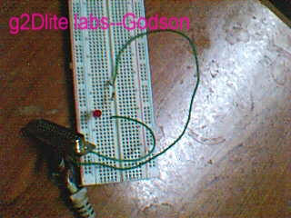
you can barely see the arrangement due to bad quality of cam I used.
After making these connections we need a program which can bring our LED to
life. here is a C program to do this task.
| #include <dos.h>
#include<conio.h>
int port = 0x378;
void on()
{
outportb(port, 0x1);
}
void off()
{
outportb(port,0x0);
}
void main(){
textbackground(7);
textcolor(4 +BLINK);
gotoxy(25,9);
cprintf("%%%%%%%%%%%%%%%%%%%%%%%%%%%%%%%%%%%%%%%%%%%%%%%%%%%%%%%%");
gotoxy(25,10);
cprintf("% bLin kiNG LED by Godson %");
gotoxy(25,11);
cprintf("%%%%%%%%%%%%%%%%%%%%%%%%%%%%%%%%%%%%%%%%%%%%%%%%%%%%%%%%");
while(!kbhit()){
on();
sound(2600);
delay(500);
nosound();
off();
delay(500);
}
getch();
}
|
If you need any clarifications on the code I used mail me. Here is a brief
explanation port=0x378 this is the usual address of LPT on IBM pcs. so the above
statement assigns 'port' variable with a value 0x378 which a hex value. Now we
need to pass logic values to this ports 2nd pin to get our LED blinking. The
following statements will do the task outportb(port, 0x1); ,outportb(port,
0x0); the first one passes a logic 1 to pin 2 of LPT which is
actually 1st data pin in it. if you wish you can change which pin to be used by
changing the value like for pin3 0x2 & so on. 0xff will bring all the pins from
pin2 to pin9 to logic one at a time . So whenever we write a logic 1 to output
port pin2 the LED connected to it will light up it self. And if we write logic 0
it'll go off. & if we repeat the process continually we can generate a blinking
effect. We can set the time delays as per our wish but don't set them to too low
values cause we are not working on a real time machine. or it may be hard to see
the blink.
The reason for using 1k resistor is that, the parallel port may be
damaged if we draw excess amount of currents from it so using low valued
resistors could be lethal to your PC. Be cautious of the this fact & if you mess
up don't blame me later. 1k is safe but I insist that you are trying it at
your own risk. don't come down to values below 500ohms. If you wish the LED to
blink with great intensity use external inverters or logic gates. Soon I'll try
that also & will upload the results here.
Of course there are even shortcut codes to do the task but I did this
to demonstrate different capabilities of C language.
Now you connect the other end of the cable to LPT port of PC .
Compile & link the above given code & run the program you'll see the LED
blinking & your PC will start to cheer you up at a popular phreak frequency of
2600Hz..

If everything goes well & your LED blinks start dancing like....
That all folks for now I'll be updating this section soon if I get enough
time, you keep visiting this site till then its bye from
 Godson
|